


One week of blog. I am glad I stuck to doing this. An outlet for me is a plus! Keeping a diary is a good idea. This is the first one I have managed to keep for a week!
9:00AM
Any positive feelings were quickly dashed this morning by the procurement of certain information, i.e. the offering of a job that I wanted to another in the company. Offering an Assistant manager a Store Manager role when A Store Manager (me) has already specifically asked for that position. What a bunch of fucking crap.
9:40 AM:
I have tried to stem the amount of swearing used in my blog, succeeding to do so thus far. I believe that is the first one. Yay. Another celebration" I apologise to anyone offended; the amount of frustration right now, when stacked, is higher than me.
Therefore some "venting" is necessary
I'm going to go watch some: ![]() Strongbad Emails to cheer me up a little.
Strongbad Emails to cheer me up a little.
Author archives: timd
Friday, 6th May 2005
Written by on May 6, 2005 .
Thursday, 5th May 2005
Written by on May 5, 2005 .
Work. Yay.
Morning trip was bullshit. Train was delayed first by 6 minutes, then by 8 then by 12. It arrived after 15 and was full any way. Next one was in 5 minutes. Lo and Behold! What do I see sitting at Redfern's Everleigh Workshops sitting in a siding? Not one, not two but three brand new shiny Millenium trains. What a fucking waste.
On and off all day I have been trying to add image tags to make a pretty table and description to my posts. It works.
Tuesday, 3rd May 2005
Written by on May 3, 2005 .
Work.
9:30 AM:
Caught up on my four favourite web comics Flintlocke, UserFriendly, PVP and Penny Arcade. Always good for a laugh. Redbull + Coffee in 2h, Awake at last... Sad really.
11:00 AM:
It's that time again, that"™s right! Stock take! Yaaaaaaaaaay!!!! ...not. Updated my store map just then. Ran around the store with my hi-lighter and checked all the sections that need re-labelling. Fun. Only about 30 ranges need labels. Glad I didn't remove the ranges from the last stock take!
2:30 PM:
I really haven"™t achieved that much today. Finding it difficult to get motivated, knowing there"™s over 3000 lines of stock that need counting in 20 days. I added some favourite links to the left hand side of the site as you may have noticed. Took me 30 mins to gather/make the damn 88x31 buttons. I gave up with Strongbad, ended up just putting a miniature image of him there, I reckon it looks good!
3:00 PM:
//---------------------------------------------------------------------------+</p>
<p>// | Library Includes: You shouldn't have to touch anything below here | // +---------------------------------------------------------------------------+
Dangerous times! Modifying the great "all-powerful" lib-common.php; The holder of many functions; the core of GeekLog! I feel elite now. My little modification was to include an extra parameter in the function "COM_optionList()". This function is a very elegant solution to creating a drop down menu from data contained in a database, just pass it your table, field names and it dumps the whole table in there and creates a drop down menu for you.
My little addition just allowed me to pass the SQL ordering suffix for the "ORDER BY" syntax, so now I can pass it "ASC" (there"™s no real point in this as its the default) or "DESC" for descending order.
Next I modified the "story.php" the part that controls the editing of stories on my website. I added the extra parameter where story.php draws the drop down menu that says wether or not to display the story on the front page. I change this almost every time while creating blog entries, hence the modification. More streamlining == teh win!
Following the successful modification of the drop down menu I set about making the size of the editing text boxes larger. They were only 50x15 characters! Way too small! Now they are a comfortable 80x25.
Monday, 2nd May 2005.
Written by on May 2, 2005 .
11:00 AM:
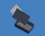
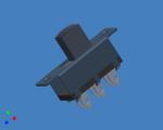
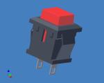
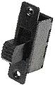
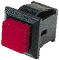
Dump iParts on web server quick! A not-so-busy morning at work. Boooooring. I did draw a slide switch and the cut-out of the zippy box in some spare time. Also, I dumped an image of the square push button for your viewing pleasure.
2:00 PM:
Finished the cut-out of the lid ready to start assembling!
3:00 PM:
Another update. We have a win. I have almost finished my 3D model.
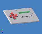
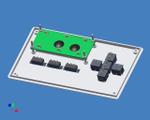
I think based on this, I may be able to put the project in the next size down Zippy Box. Then it will be a bit smaller, then again, it's: a) a prototype and b) not supposed to be hand-held. There will be a remote release attached to this as well for manual shooting. The remote-remote will be smaller and "hand-held" with two buttons. One button will control AF/AE (Auto Focus/Auto Exposure) depending on the mode of the camera and the remote release, the other will control the shutter.
So that's done, now what. Next I have to draw the connector I will be using. It is an 8 pin mic plug. Very heavy duty and solid. 8 pins for redundancy, only three will be used to start with. Depends if I add pretty LEDs and crap to the remote...
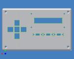
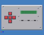
The layout. Yes, it's not even. That will come later.
Components:
5 x P7552 - Square push buttons.
These will be used for navigation through the menu system. They will be up, down, left, right and in the center; set.
3 x P7610 DPDT Slide Switches.
The first will be used to switch between "set" mode and "run" mode. The second will be used to set "Manual" or "Controller" shooting. The third will control the backligths and LEDs, incase they interfere with a low-light shot.
The menus are designed. I just need to code the damn thing now. But first, the prototype!
Sunday, 1st May 2005.
Written by on May 1, 2005 .
I can't believe it's May already! Made some pancakes for breaky, I got a good recipe off a forum that I frequent called Overclockers Australia (requires registration). There is a section of the forum called "Geek Food" that the forum members post queries and ideas about different foods.
Finishing off the drawing of the square push-button. Its turned out OK. I detailed the internals, they will be left out to save resources when I make my 3D prototype.
5 PM:
Decided to start the Zippy. The main body and the lid of it is done, just detailing the board holding slots on each side. Taking about 50-60 seconds per line because of a repeating pattern, slows things down quite a bit!
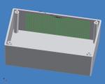
As you can see in this image, theres a big long repeating pattern. Takes ages to re-draw.
Well it's sucking down 50% of my CPU time. Thats a P4 2.4 with 1Gb of RAM. I don't even want to imagine how long a re-draw would take on my poor old Laptop... (A P3 550.). It seems theres a *magical* tick box that stops the square patterns taking a week to calculate and re-draw. It's the "Associative" tick box. This means it just makes an array copy of the selection and it doesn't update them when the original changes... yay.
Finally we have zippy boxage.
Lots of waiting and two crashes, here it is!
Saterday, 30th April 2005.
Written by on April 30, 2005 .
Morning Update... Yeah. Going to have to try to keep this updated! Surely there's something interesting to add...
Ah Ha! Heres something!
This morning I checked out the ESA site after hearing about Mars Express on TV last night. There was a documentary on the ABC about the various mars missions. Very cool, anyway, I found the Mars Express page at ESA. There are some incredible surface pictures coming from the orbiter, it has a HRSC mounted on it. That's "High Resolution Stereo Camera". A very cool piece of kit.
The HRSC uses a special set of 9 CCDs consisting of a single line of 5184pixels each. For imaging there are three channels red, green, blue, near infra-red. Next there are two "photometry" channels, they are used for sensing brightness to determine the composition of the surface these are angled just under 18 degrees either side of the perpendicular. Heres the tricky part, the other 3 CCDs. To create 3D data based on imaging using a method called "photogrammetry" you need a front-looking, back-looking and down-looking image. Positioned perpendicular to the surface is one CCD called the "Nadir" channel or downward looking channel, either side of the nadir at +/-18.9° are two more channels for the forward-looking and backward looking images.
That's a HUGE image, they must decrease the amount of data they have to send, as bandwidth and time are limited. They do this by using a 2x2 pixel summary. This means they average out the values of each 2x2 block of pixels reducing the data size 4 fold.
There are some really stunning images coming off that orbiter. Check them out in the Mars Express Gallery
I like learning stuff. Just wish I could keep it in my head! I hope they find water on mars ... that's the mission of Mars express, well one of the objectives. It is equipped with RADAR that can scan up to 5km below the surface! Water on mars. Damn that would heat things up. It would very quickly start a new "Space Race" I think. Race to mars. Hrm... Mars "look" like a hot planet; all orangy and desert looking. The fact is its incredibly cold, -113°C to 0°C yay! I'm thinking shorts.
Arvo:
Did some shopping around today. We bought "Monopoly". Finding things to do together is a big plus. Kel (my Fiance) and I have lots in common but not any hobbies in common, difficult to explain. Meh, I won't try... Movies, Monopoly and Barbecue tonight!
Time to sharpen my knife and try out my new chopping board. A very nice Wiltshire board I figured if we are going to buy good knives, then I need to replace my crappy, split, warped board...
Night:
Well the er... chopping board works, as far as chopping boards work. My "cutting experience" wasn't what I could call "enhanced" by any means... Meh. It seems I will be having an Audience for my barcueing. The flat across the way have like 20 people over on their patio.
Friday, 29th April 2005.
Written by on April 29, 2005 .
I haven't really been doing all that much. Mainly working and drawing switches and stuff in Inventor. I am creating each component for use in my prototype Remote Release for my DSLR. It's going to be programmable so you can do long exposures, multiple timed shots etc.Once I have completed models of each component I will be able to create a prototype in Inventor to see how everything will fit. It's a hell of a lot easier than drawing it on paper or actually building it to see if it will all fit and look ok.
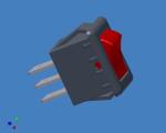
At the moment I am going to start drawing a square push button that I bought from Dick Smith. I also have to draw the Zippy box I am going to use. The other thing I have to investigate is taking apart some Neon lit rocker switches and replacing the Neon with an LED so it can be lit when used with low voltages.
I have already drawn a different push button; I think it will be too high off the panel though, so that's why I bought the smaller square ones to try. The only advantage of the taller ones is they use an 11mm round hole, that's a lot easier than the square buttons where you must drill a 9mm hole and file or nibble it into a square hole.
The LCD for the project is already modelled. It's an Ampire brand 16x2 with Backlight. I am still thinking about how that's going to be mounted. I am trying to decide what lid to use on the Zippy box. I could use just the plastic lid, just the thin Aluminium lid or both. If I use just the plastic the LCD will be in-set 2mm, it will look pretty deep. On the other hand I could use just the Aluminium lid. That I think would be pretty flimsy on its own, but would look nicer. If I used both then I would cut a bigger hole in the plastic so the LCD could fit but the top of the LCD would sit flush with the bottom of the Aluminium panel; giving me the best of both worlds.

The other thing I want to investigate is creating/sourcing a 2 stage button for manual shooting. I was thinking of using a pair of micro switches at different heights. That would probably be difficult to set up and achieve consistant switching from. It might need a de-bounce circuit as its going to be used on a diital input.
Start A Blog.
Written by on April 27, 2005 .
New Site... ...Again.
Written by on April 27, 2005 .
I had started writing a very basic CMS (Content Management System). The CBF factor became too high so I started trying open-source CMSs. First there was Xoops. Xoops is pretty cool and very happy looking. It works very well. I have no complaints on the CMS side of things. There was the compatibility with Gallery 1.5 RC3. It was there but wasn't very complete. The module to add your gallery into it was pretty old, being based on 1.3.3 or something. The other thing was support. I submitted some bits and pieces on the forum of the module and received no response =(
Next PostNuke. That lasted about 2 hours then I junked it because I discovered Mambo.
Mambo is VERY cool. I found it had a very round about way of posting articles though. This is truly an amazing little piece of kit, every facet of your content and layout is customisable though configs and themes. Very, Very Cool. But not for me. This also has the Gallery Compatibility boggle. Same as Xoops I got it to work. *I* could view the gallery but the filed based users and groups of gallery prevented the public (non-registered users) from viewing.
A week later I decided to try GeekLog. This is a very elegant, very streamlined solution. No fancy config pages just the necessities. The guts of it are configured from two PHP files, the rest is module based. Each module has it's own configs but some have built in config pages. The layouts are set using HTML based themes containing tags for each element you want to load in that particular area. Once I got things figured out I created a new gallery, first standalone then I integrated it with GeekLog. BAM! Worked first time. All I had to do was alter my gallery config to tell Gallery where GeekLog's files were living and that was it. Straight away, no bugs, no issues, no boggles - a relief after all the previous experimenting. This was the *last* option for Gallery compatibility, other than writing from scratch. Next thing to do, once I clean up all my articles that I brought across, is to finish customizing GeekLog so it looks the way I want it to.
I have already done the bulk of it, colour scheme, layout etc. It just needs a few hours of solid "testing and tweaking". I also need to write my "CBF Speaker Stand" article about my Low CBF Factor speaker stands =)
LCD Faceplate Mod
Written by on March 16, 2005 .
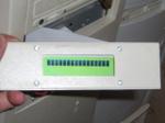
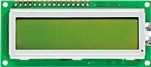
So you wanna put an LCD on the front of your case? Heres How! This is an updated version of my original article from way back in may 2002. Stuff you will need: An LCD with a HDD4470 controller. This particular controller is very easy to interface with and is also commonly available. We will be using the DSE (Dick Smith Electronics) Z-4172(Backlit). The preference goes to the DSE LCDs because the dimensions are different. My drawings will be based on the footprint of the two DSE LCDs. If anyone knows anywhere else I can source LCDs let me know, I will compile a list at the bottom of the article with responses I get.DSE only sell the two versions. Altronics have 16x2 displaysin two flavours.
 Z-4170(Not Backlit) |
 Z-4172(Backlit) |
| Datasheet:ac-16b. | |
| Manufacturer: | Ampire |
| Lines: | 2 |
| Chars/Line: | 16 |
| Datasheet:ac-16b. | |
| Manufacturer: | Ampire |
| Lines: | 2 |
| Chars/Line: | 16 |
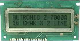 Altronics Z-7000A(Not Backlit) |
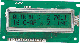 Altronics Z-7011(Backlit) |
| Datasheet: |
|
| Manufacturer: | Not listed. |
| Lines: | 2 |
| Chars/Line: | 16 |
| Datasheet: |
|
| Manufacturer: | Not listed. |
| Lines: | 2 |
| Chars/Line: | 16 |
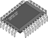
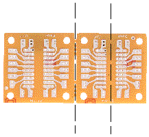
The HDD44780 LCD Controller ![]() hdd44780controller.pdfOnce again my favourite chip carrier board H-5601.You can also use prototype board or even etch your own board if you can be bothered =)
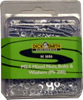
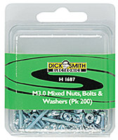
hdd44780controller.pdfOnce again my favourite chip carrier board H-5601.You can also use prototype board or even etch your own board if you can be bothered =) 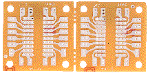 H-5601 The mounting gear: To mount the LCD I used four M2.5 by 25mm bolts with the appropriate nuts. To mount the socket on the back of my PC for the parallel port I used M3 by 12mm bolts and nuts. You can get these from DSE too and most electronic stores or even the hardware. H1200 - m2.5 hex nuts pk25 H1212 - m2.5 x 25mm pk25 H1686 - m2.5 mixed (pictured) H1325 - m3 hex nut pk25 H1326 - m3 hex nut pk200 H1064 - m3 x 12mm pk25 H1065 - m3 x 12mm pk200 H1687- m3 mixed (pictured)
 |
 |
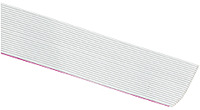
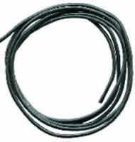
Cable:Power - General purpose medium weight hook-up wire. I used black =)Data - 25 Way ribbon cable. DSE, Jaycar etc, you could also recycle an old IDE/SCSI cable from the crap bin...
| W2748 | W2242 |
 |
 |
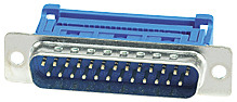
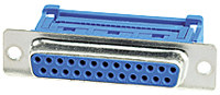
Plugs and Sockets:25 way Female x 1 - Ribbon style25 way Male x 2 - Ribbon style4 pin 90 degree header pins (Floppy drive style). I found some at Altronics, not 90 degree, but hopefully they are the same pitch. I have ordered some anyway, I will see. The picture is incorrect, but it will give you an idea what I mean. If you cant find any, do what I did in my original LCD and de-solder some from an old floppy drive.
| P2693 | P2694 | P5492 (Altronics) |
 |
 |
 |
Components: 100Kohmpot, I used a miniature trim pot (DSE Cat: R-1929)100ohm pot, same (DSE Cat: R-1947)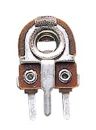 NB:Pot = potentiometer. Tools Needed:
| Soldering Iron: | Hopefully with a fine tip, solder pads on the LCD are pretty damn close |
| Screwdriver (Phillips): | Used for securing screws |
| Jewellers Screwdriver (flat): | Used for tweaking pots when done |
| Side Cutters/Wire Strippers: | Stripping/Trimming wire |
| Scissors: | Cutting the ribbon cable |
| Stanley knife or blade: | Handy; Deburr/Trim. |
| Drills: | 3mm for the M2.5 holes and 7mm for the nibbler to fit through |
| Nibbler or File: | Cutting out the front panel, Filing the edges of your prototype board or chip holder board after its been cut. |
| Small spanner, small shifting spanner or pliers: | Doing up the nuts on the LCD |
| Hacksaw: | Cutting your prototype board or chip holder to the right size |
Space: You will need about 35mm clearance from the front of the case in the 5.25" bay. This is including the thickness of the blanking panel. I have a HDD behind my LCD, it just makes it.? Design: I drew the LCD footprint to scale and then the inside dimensions of the back of the blanking panel. I took the measurements off the datasheet and drew it to scale in CAD. Paint just doesn't cut it. That way when you print, its to scale. What I did here was printed the drawing to scale, cut it out, stuck it inside the blanking panel. I then drilled and nibbled/filed. I had to adjust the template a few times, it moved around. It doesn't work as well for large holes, like it did with the USB ports.I read in EA (Electronics Australia) a good method for doing it. It involves a similar method to mine, however before they drill, they cut the outline of what is to be nibbled with a Stanley knife/Blade. They then drill, remove the template and then nibble/file. I am going to try this on the one I will build. Doing it this way means that there is no way of it moving. It doesn't move that much when drilling, however when nibbling/filing it can move. Tip: Cleaning holes drilled in plastic - or anything for that matter!:When you drill a hole, you almost always get crappy burrs. There is a really good way to fix this that my dad showed me when I was little. I have always used it since then.What you do is use a large diameter drill (larger than the hole, at least 2x) or a counter-sink bit. Pressing lightly you twirl the bit in your fingers while the tip of it is sitting in the hole you drilled. This removes the swarf/burrs and gives you a nice tiny little champher around the hole. When you do this on metal you may have to press a little harder. The Circuit Board:CAUTION: Remember the LCD is STATIC SENSITIVE!There are 14 tiny solder joints that are great fun to do. NOT. This is on the LCD. Take extreme care not to overheat the LCD.Snap your chip holder pair of boards in half, then cut your single board in half down the centre. You can cut the board using a hacksaw (not a h4x0r). The other option is scoring it (making a cut in it) on both sides, then placing it in the vice with the lines level with the jaws of the vice, then snapping it. Sometimes it doesn't work, but other times, you get a nice neat edge. Once you've done this, file the edge flat.
|
 |
The circuit its self:This is based on a couple of diagrams I have seen. FAQ: Q:Can I get a blue back lit LCD like in phones. A:Yes and no, hard to get pre-made, you can get blue backlighting and do it yourself though. Don't you worry, as soon as I find where I can get some in Australia. I will let you all know =) Q:What can I display on the LCD? A:Anything you want. If you can find or make software to do it. I have some visual basic software that I wrote for it to display different stuff. There are also many WinAmp LCD Plugins to display current song/bit rate etc.
Database Driven!
Written by on Feb. 22, 2005 .

I have been very busy coding and now the website is now entirely database driven. All I have to do now is create some pretty admin/maintenance pages so I dont have to go to the SQL shell every time I want to post news! Menus and content are controlled by the database! Sweeet =)
It Begins!
Written by on Feb. 13, 2005 .
ZBox is now live and can actually stay live. Its now not too noisy to leave on at night. www.zagadka.org is live! See this mod I did to fix the noise problems.'