Archives October 2011

Saturday 29th October 2011 - 23:48:13

Reverser Relay

I managed to make it out to the lab for a bit today.

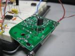
I added a relay to the kids electric ride on Jeep replacing on/off with forward/reverse. They never turn the damn thing off anyway! I bypassed the on/off switch and cabled it separately. Originally the on/off and "go" buttons were in series. The on/off now energizes a relay for reverse, when unpowered the NC position on the relay is forward. I used a simple DPST reverser configuration where the power enters the NC terminals then crosses over to the NO terminals creating a polarity switch. The motor is fed from the centre common terminals.

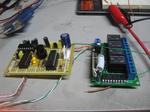
Also on the list - a white noise generator. After messing around a few nights ago and not getting anywhere, I tried another circuit. This time using BC548s and a 12V supply. One BC548 is reverse biased and the E-B junctions zener effect is used as a noise source. The base of the reverse biased BC548 is then fed into the base of another BC548 to be amplified and then coupled with a 10uF cap to another BC548 for further amplification. At one point while I was messing around it was receiving radio - probably from the audio amp section. The whole thing is on a bread board, so its not that protected from interferance.

Monday 17th October 2011 - 07:38:30

Chip

Owner finally decided to fix the sewer properly after 3 months. Yaaay

Saturday 15/10/2011

Chip

Unproductive Saturday. Watched the plumber try to jet blast the sewer most of the day as well as trying to help him with some bugs in his jetblast system. He just replaced the water tank in his truck and hadn't drilled a breather yet. The high pressure pump tried to turn the plastic drum inside out - and nearly did... We had to reprime the pump too because it was full of air.

Spent the rest of the day on the veranda with a beer watching the kids play (and giving hugs to stem crying / breaking up their fights =P )

Monday 3rd October 2011 - 18:45:31

IMG_1164

Today I messed around with the "f88 and got the code working to push updates to the three multiplexed displays in parallel. The controller, once completed, will be fitted to my dummy load. One A2D will read the voltage on the 1R shunt giving me current, the other will measure the input voltage. During the update process, the pic multiplies these two and gives a third readout in watts. These three figures are then pushed out to three shift registered with linked clocks and latches. Three four digit displays with just 5 IO.

Saturday 1st October 2011 - 18:51:01

Chip

Today I worked on the door counter project. I was inspired by Dave Jones' EEVBlog #204 and decided to do some of the math (which I'm really not great at and should practice!) instead of just throwing a pot in and then measuring it after.

Because of the overhead in the encoder/decoder arrangement and wireless, a pulse of at least 250ms is required before the other end reacts. This took some messing around with the scope and poking with a bit of wire to work out. When the relay on the door laser clicks, the pulse is very short, maybe 20-30ms.

To stretch out the pulse I used the 555 timer in monostable mode. Pin 2 of the 555 is pulled high by a 10k resistor. The output (pin 3 of the 555) is tied via a resistor to the base of a transistor. The transistor, an NPN BC548, is sitting across the pushbutton on the transmitter with its collector on the +5v side. When a falling edge (high to low transition) is detected on pin 2 of the 555, pin3 goes high for a fixed length pulse (unless pin 2 is maintained low for longer than the pulse time). The pulse length can be calculated using t (time) = 1.1RC.

With a desired pulse time of 250ms we can work out the resistor and capacitor required. I chose 10uF to start with and worked out R from there.

Here is a scope grab. It worked out pretty close.

Saturday 1st October 2011 - 09:14:38

Chip

Grass! It's like the day of the Triffids here. I couldn't mow last weekend because it rained. I've been thinking more and more about a project to use servos. I think a small lawnmower engine PID with throttle on a servo would be cool which regulated the revs. Later, a full RC mower.

I've got to finish off the door counter (which I mentioned as finished in an earlier blog). The counter hardware it's self is finished, but I need to write software for the linux box and I also need to make TX/RX arrangement to send the door clicks to the counter. The original plan was to have the whole unit next to the door and run a long serial cable. I've sinced decided that we're going to use some 315MHz TX and RX modules from work which means I need to make an monostable oscillator to extend the pulses long enough to make it through the RX and TX modules - if they are too short, they don't register at all. I am thinking at least 100ms.

Daily archives