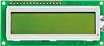
So you wanna put an LCD on the front of your case? Heres How! This is an updated version of my original article from way back in may 2002. Stuff you will need: An LCD with a HDD4470 controller. This particular controller is very easy to interface with and is also commonly available. We will be using the DSE (Dick Smith Electronics) Z-4172(Backlit). The preference goes to the DSE LCDs because the dimensions are different. My drawings will be based on the footprint of the two DSE LCDs. If anyone knows anywhere else I can source LCDs let me know, I will compile a list at the bottom of the article with responses I get.DSE only sell the two versions. Altronics have 16x2 displaysin two flavours.
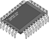
The HDD44780 LCD Controller  hdd44780controller.pdfOnce again my favourite chip carrier board H-5601.You can also use prototype board or even etch your own board if you can be bothered =)
  H-5601 The mounting gear: To mount the LCD I used four M2.5 by 25mm bolts with the appropriate nuts. To mount the socket on the back of my PC for the parallel port I used M3 by 12mm bolts and nuts. You can get these from DSE too and most electronic stores or even the hardware. H1200 - m2.5 hex nuts pk25 H1212 - m2.5 x 25mm pk25 H1686 - m2.5 mixed (pictured) H1325 - m3 hex nut pk25 H1326 - m3 hex nut pk200 H1064 - m3 x 12mm pk25 H1065 - m3 x 12mm pk200 H1687- m3 mixed (pictured)
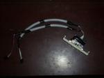
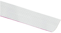
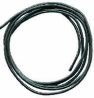
Cable:Power - General purpose medium weight hook-up wire. I used black =)Data - 25 Way ribbon cable. DSE, Jaycar etc, you could also recycle an old IDE/SCSI cable from the crap bin...
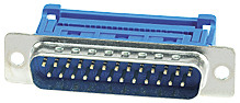
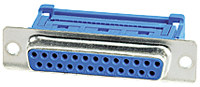
Plugs and Sockets:25 way Female x 1 - Ribbon style25 way Male x 2 - Ribbon style4 pin 90 degree header pins (Floppy drive style). I found some at Altronics, not 90 degree, but hopefully they are the same pitch. I have ordered some anyway, I will see. The picture is incorrect, but it will give you an idea what I mean. If you cant find any, do what I did in my original LCD and de-solder some from an old floppy drive.
Components: 100Kohmpot, I used a miniature trim pot (DSE Cat: R-1929)100ohm pot, same (DSE Cat: R-1947)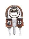 NB:Pot = potentiometer. Tools Needed:
| Soldering Iron: |
Hopefully with a fine tip, solder pads on the LCD are pretty damn close |
| Screwdriver (Phillips): |
Used for securing screws |
| Jewellers Screwdriver (flat): |
Used for tweaking pots when done |
| Side Cutters/Wire Strippers: |
Stripping/Trimming wire |
| Scissors: |
Cutting the ribbon cable |
| Stanley knife or blade: |
Handy; Deburr/Trim. |
| Drills: |
3mm for the M2.5 holes and 7mm for the nibbler to fit through |
| Nibbler or File: |
Cutting out the front panel, Filing the edges of your prototype board or chip holder board after its been cut. |
| Small spanner, small shifting spanner or pliers: |
Doing up the nuts on the LCD |
| Hacksaw: |
Cutting your prototype board or chip holder to the right size |
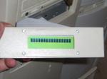
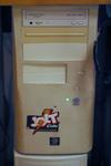
Space: You will need about 35mm clearance from the front of the case in the 5.25" bay. This is including the thickness of the blanking panel. I have a HDD behind my LCD, it just makes it.? Design: I drew the LCD footprint to scale and then the inside dimensions of the back of the blanking panel. I took the measurements off the datasheet and drew it to scale in CAD. Paint just doesn't cut it. That way when you print, its to scale.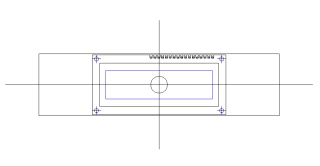 What I did here was printed the drawing to scale, cut it out, stuck it inside the blanking panel. I then drilled and nibbled/filed. I had to adjust the template a few times, it moved around. It doesn't work as well for large holes, like it did with the USB ports.I read in EA (Electronics Australia) a good method for doing it. It involves a similar method to mine, however before they drill, they cut the outline of what is to be nibbled with a Stanley knife/Blade. They then drill, remove the template and then nibble/file. I am going to try this on the one I will build. Doing it this way means that there is no way of it moving. It doesn't move that much when drilling, however when nibbling/filing it can move. Tip: Cleaning holes drilled in plastic - or anything for that matter!:When you drill a hole, you almost always get crappy burrs. There is a really good way to fix this that my dad showed me when I was little. I have always used it since then.What you do is use a large diameter drill (larger than the hole, at least 2x) or a counter-sink bit. Pressing lightly you twirl the bit in your fingers while the tip of it is sitting in the hole you drilled. This removes the swarf/burrs and gives you a nice tiny little champher around the hole. When you do this on metal you may have to press a little harder. The Circuit Board:CAUTION: Remember the LCD is STATIC SENSITIVE!There are 14 tiny solder joints that are great fun to do. NOT. This is on the LCD. Take extreme care not to overheat the LCD.Snap your chip holder pair of boards in half, then cut your single board in half down the centre. You can cut the board using a hacksaw (not a h4x0r). The other option is scoring it (making a cut in it) on both sides, then placing it in the vice with the lines level with the jaws of the vice, then snapping it. Sometimes it doesn't work, but other times, you get a nice neat edge. Once you've done this, file the edge flat.
|
 |
The circuit its self:This is based on a couple of diagrams I have seen.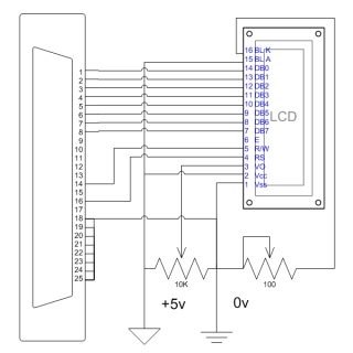 FAQ: Q:Can I get a blue back lit LCD like in phones. A:Yes and no, hard to get pre-made, you can get blue backlighting and do it yourself though. Don't you worry, as soon as I find where I can get some in Australia. I will let you all know =) Q:What can I display on the LCD? A:Anything you want. If you can find or make software to do it. I have some visual basic software that I wrote for it to display different stuff. There are also many WinAmp LCD Plugins to display current song/bit rate etc.


