Tag archives: electronics

Friday, 4th January 2013 - 22:57:21

Chip

Had a great day out in the shed today. Wrote a bit of code, played with a bit of electronics =)

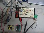
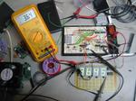
I started working on a solar charger which will charge a(n) SLA battery(ies). I have 4 small panels which I can make use of for this. The idea is that it logs the incoming voltage and current off the panels. It will allow me to play with the ADCs a bit and also learn a bit about opamps - I plan on using a shunt resistor on the high side with an op amp configured in differential mode to determine the voltage drop and therefore the current.

I may eventually use this to run a small 60W server if it has the guts.

Thursday, 25th October 2012 - 22:43:10

Python Logo

It's been a while...

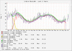
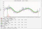
I decided to finally spend the time and fix the data in the main RRD for the temperature logger. At one point digitemp config was re-written and the order of the sensors was skewed.

Before: After:

Python to the rescue. A quick script to load the dump up and transpose the sensor readings after the datestamp of the glitch. It looks a lot better now. I may just rip out that fermenter column all together, it has maybe a handfull of sensor readings over the 3 years.

Monday 28th November 2011 - 08:44:21

Chip

Went on a fixing mission this weekend. Rehung doors, fixed broken kids stuff (new wood leg for their little chair), re-mounted sunken light switches and all sorts of stuff. I removed the Roman rings from the kids swing set and added a new swing – so the wood working gear got a workout – poor little router hasn't had a good run for months. I used some cable pull rope to hold up the swing with eye splices at each end – although I had to go and look up the eye splice again because I messed it up initially... On Friday I borrowed a bench top LCR meter to measure the resistance and inductance of the armature and field windings of the VW generator which is going to be converted to a traction motor. Only problem was I didn't go and get the generator! Here is a screen dump of the motor control circuit graph:

Monday 3rd October 2011 - 18:45:31

IMG_1164

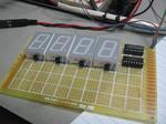
Today I messed around with the "f88 and got the code working to push updates to the three multiplexed displays in parallel. The controller, once completed, will be fitted to my dummy load. One A2D will read the voltage on the 1R shunt giving me current, the other will measure the input voltage. During the update process, the pic multiplies these two and gives a third readout in watts. These three figures are then pushed out to three shift registered with linked clocks and latches. Three four digit displays with just 5 IO.

Saturday 1st October 2011 - 18:51:01

Chip

Today I worked on the door counter project. I was inspired by Dave Jones' EEVBlog #204 and decided to do some of the math (which I'm really not great at and should practice!) instead of just throwing a pot in and then measuring it after.

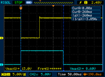
Because of the overhead in the encoder/decoder arrangement and wireless, a pulse of at least 250ms is required before the other end reacts. This took some messing around with the scope and poking with a bit of wire to work out. When the relay on the door laser clicks, the pulse is very short, maybe 20-30ms.

To stretch out the pulse I used the 555 timer in monostable mode. Pin 2 of the 555 is pulled high by a 10k resistor. The output (pin 3 of the 555) is tied via a resistor to the base of a transistor. The transistor, an NPN BC548, is sitting across the pushbutton on the transmitter with its collector on the +5v side. When a falling edge (high to low transition) is detected on pin 2 of the 555, pin3 goes high for a fixed length pulse (unless pin 2 is maintained low for longer than the pulse time). The pulse length can be calculated using t (time) = 1.1RC.

With a desired pulse time of 250ms we can work out the resistor and capacitor required. I chose 10uF to start with and worked out R from there.

Here is a scope grab. It worked out pretty close.

Saturday 1st October 2011 - 09:14:38

Chip

Grass! It's like the day of the Triffids here. I couldn't mow last weekend because it rained. I've been thinking more and more about a project to use servos. I think a small lawnmower engine PID with throttle on a servo would be cool which regulated the revs. Later, a full RC mower.

I've got to finish off the door counter (which I mentioned as finished in an earlier blog). The counter hardware it's self is finished, but I need to write software for the linux box and I also need to make TX/RX arrangement to send the door clicks to the counter. The original plan was to have the whole unit next to the door and run a long serial cable. I've sinced decided that we're going to use some 315MHz TX and RX modules from work which means I need to make an monostable oscillator to extend the pulses long enough to make it through the RX and TX modules - if they are too short, they don't register at all. I am thinking at least 100ms.

Sunday 11th September 2011 - 23:26:32

Chip

I have finished off the door counter for work. We will see how helpful it is. I might put in the serial link today so that I can link it into the server.

Now to write a python daemon to monitor the clicks on the serial port!

Friday 26th August 2011 - 08:51:39

Chip

I am currently working on a door counter. I have based it on the 16f84A (I bought a tube of them years ago before I worked out they weren't really that great). In keeping with the ancient PIC, I found ancient schmitt trigger to debounce. The TP4304. Its stamped '78. I scored a bunch of old CMOS from a closing electronics store.

http://www.datasheetarchive.com/dl/Datasheets-112/DSAP0044783.pdf

Sunday 21st August 2011 - 18:22:09

IMG_1166

Got lots of work done on my 4 digit multiplexed display. The prototype is up and running with an ADC demo on the pic. It's running 100hz refresh rate with 5hz data refresh rate.

Tuesday 9th August 2011 - 18:02:42

Lots of TG Watchdogs ready to go!

I have had a request to prepare a TG watchdog for installation inside a PC. To do this I am using the router to supply it power (as normal) and I have prepared a ribbon cable to go straight into the mainboards COM IDC header - rather than piggybacking ouside to a D9 socket and back in.

I also had the idea to use the TG watchdog as a means of powering down the box it lives in. Because it is powered externally to the server it lives it, it could reset or power down the system. I have some stuff I bought from mouser - 2 way inline SIL sockets and plugs. I'll have to post photos and part numbers. You could make a wedge cable to short the power or reset pins on the mainboard while leaving the button function intact.

Wednesday 27th July 2011 - 07:52:47

Chip

I now have Hi-Tech C running under piklab. I'm glad that I tried it now.

After messing around for an evening or two with a stupid problem where bitwise OR assignments "|=" on PORTA and reading the value on PORTA fails, I decided that maybe SDCC was bugged. The OR would appear to work, but on closer inspection they actally zeroed the byte I was working on and only set the single bit that I was specifying. I installed MPLAB 8.73 with the Hi-Tech C compiler for 10/12/14/16 MCUs. There was trouble initially with wine as the picc.exe executable lived under "Program Files", So I moved the folder down to the home directory. This brought me a step closer as piklab verified the files exist - when it came to compile time piklab still tried to execute the linux executable rather than the .exe. I symlinked sdcc.exe to sdcc and libr.exe to libr and it now works fine.

Straight away I tried a compile (which failed) and then started the port from sdcc to picc. Once I had finished, the project built ok and I burned the hex to the pic (an 'f88). Lo and behold the same error occurred!

The code I used was originally an experiment with the adc which I wrote previously to try out SDCC. After combing the net I found a FAQ on the Hi-Tech website which described exactly my fault! I had a read of the FAQ and then checked out my code. Doh! I had remmed out the ANSEL declaration rather than implicitly setting it to 0. Facepalm.

Saturday 23rd July 2011 - 20:15:43

Chip

Last night I decided to try SDCC again. It works much nicer than the last time I tried it. It also managed to make it work correctly with Piklab.

I have the USART and basic stuff running on a breadboarded TG watchdog.

Thursday 7th July 2011 - 20:38:20

Chip

I am learning LTSpice and have finally worked out how to sweep a resistor value over time in an LTSpice simulation. I tried all sorts of stuff to make it work, but didn't think of this novel way of doing it. Drive the resistance by multiplying the total resistance by a 0-1v sweep (and add say 0.001 so LTSpice doesn't cry). Unfortunately I can't take credit for this idea myself - it came after lots of googling and forum trolling. I've incorporated this sweep into my new constant current load simulation. This sweep starts after a delay of 2s.

The first part of the simulation (first 2s) concentrates on the low battery indicator. The vbattery voltage sweeps from 12v up to 24v over 2s so that we can see the battery voltage cross the low battery set threshold and the vlowled indicator fall.

In the top plot area you can see the traces for the battery after the resistor divider (vlowsens), the low battery threshold voltage set with a zener diode (vlowset), the output from the opamp to drive the low battery LED (vlowled) and the +15v output from the LT1121.

In the middle plot we can see the amount of current being sourced and by multiplying the voltage on the high side of R1 by the current on R1, we can see the power in watts.

The bottom plot area shows the linear response of the pot simulating the rotation of the dial for its full range over 10 seconds. It crosses over in the middle where the wiper is at exactly 50%.

There are also a few more notes and photos in the gallery.

Wednesday 1st June 2011 - 12:02:53

Chip

Got a few bits on clearance from Rockby. Large 7 segment LED modules and some SMD 5V relays. Cool.

Saturday 14th May 2011 - 18:39:34

Chip

I've started building my DSE signal generator kit. I bought the thing literally years ago, when I still worked there - before Woolworths destroyed the staff discount.

It will be built into a nice sloped console box and will include the DSE frequency counter kit.

Friday 27th May 2011 - 07:11:18

Chip

Finally, my 10 turn pot has arrived from Element 14, I can complete my EEVBlog based active load! It was out of stock and had to be shipped from the US. Last week I got the rest of my stuff from Element 14 including a 0.1R 25W aluminium clad resistor, an LM3302 comparator to fix Dad's strobe tacho, some CMOS 4000 series to play with - 40106 (hex schmitt inverter), 4030 (quad xor), 4027 (dual J/K flipflop), 4081 (quad and).

Saturday 7th May 2011 - 16:51:41

Chip

Added photos to gallery:


Saturday 1st May 2010 - 22:31:39

Chip

May Already?!

Kel had lot to do today so I looked after the Kids. If only I could get them to dig in their sand pit and not in the dirt.

I showed Liam an episode of The Mysterious Cities Of Gold, both he Emily were GLUED to it. The Mysterious Cities of Gold is a cartoon that was on when I was little in the late 80s. I used to like it alot. Liam even said that he likes it better than BEN 10!

I had some time today to build an ICSP attachment for programming 18 pin pics. My JDM serial programmer doesn't seem to cut it any more. I designed the link cable from the ICD2 so that it fits the headers on the attachments for the JDM so I can now do 18, 28 and 40 pin pics. The JDM has become unreliable for some reason, I have trouble verifying the code once it's written - and it takes aaages to write. The ICD2 takes only a few seconds.

I built up another MAX232CPE serial prototype circuit on the breadboard for my next round of tinkering with the 16f88. Although, tonight I did manage to get the UBW firmware D (USB CDC) to compile after lots and lots of messing around on and off over the past few weeks. If I can get that built and the bootloader then I can go direct to USB rather than serial. I have a Sparkfun UBW with the 18f4550 on it and also two 18f2550s for breadboard work.

The workflow using the ICD 2 is going to be different. I am used to pulling the chip out of circuit to program it. The next target is to test the ICD functionality - I've never tried it before.

I added mod_python to apache on my server at home so I can play with Django. I went through the first two parts of the tutorial and it was pretty cool (using the dev server). Under mod_python the paths are screwy - I must have misconfigured it. Will go back to it later! Oh - the built in dynamic admin functionality is just awesome. It takes so much crap work out of putting up the back end of a site - forms, fields, validation etc etc (all the tedious stuff)
Tuesday 5th April 2011 - 21:36:22

Chip

I've got myself a freshly imported Rigol DS1052E! It's got a Chinese manual, but meh. There is a PDF version of the manual in English if I really want it. I guess watching Dave play with all his scopes over at EEVBlog convinced me to get one.

The thing is awesome! I love it. DSO is entirely new to me. I've currently got a Dick Smith 60MHz CRO. I think my favorite thing so far is the single shot triggering and the timebase zoom it has, where you can show a magnified (by time) view of the triggered waveform below the normal display.

Thursday 4th November 2010 - 21:41:15

Chip

I have just put my first order into Mouser. Most of the TG board is based around what I can get from Electus and Mouser. I also got a few extra bits to play with.

I am building a dummy load based on Dave Jones' design from EEVBlog, so I need a 10 turn 50K linear pot.

Other goodies:

  • RGB SMD LEDs
  • 20 and 24 meg crystals for my new pic 18f2550
  • A few SMD USB mini-B connectors to evaluate
  • 0.1R 25W aluminium clad resistor