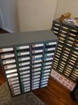
The remote power supply for the cherry lights and the RGB garden lights is now complete. This will eliminate one sonoff which was previously used to control the cherry lights on the mains side.
Saturday, 3rd November 2018 - 18:32:09
Written by on Nov. 3, 2018 .
Saturday, 27th October 2018 - 19:54:46
Written by on Oct. 27, 2018 .
Saturday, 13th October 2018 - 14:08:33
Written by on Oct. 13, 2018 .
Friday, 7th September 2018 - 17:32:24
Written by on Sept. 7, 2018 .
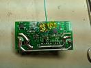
Created a power supply controller for the garden lights to turn on and off the set of standard cherry lights and supply the IOT garden lights with power also. Each (24vAC and 12VAC) are controllable via relays. It also has a rectifier and DC-DC convers to supply 5V and 3.3V for other projects and the ESP8266 controlling the PSU.
Monday, 3rd September 2018 - 19:28:01
Written by on Sept. 3, 2018 .
Tuesday, 14th August 2018 - 22:01:00
Written by on Aug. 14, 2018 .
Monday, 13th August 2018 - 14:38:01
Written by on Aug. 13, 2018 .
Sunday, 5th August 2018 - 10:57:36
Written by on Aug. 5, 2018 .
Saturday, 14th July 2018 - 15:51:50
Written by on July 14, 2018 .
Sunday, 8th July 2018 - 18:15:51
Written by on July 8, 2018 .
Sunday, 8th July 2018 - 14:16:43
Written by on July 8, 2018 .
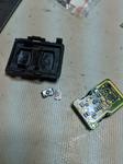
The remote lock/unlock for the car has these weird surface mount buttons on them. They have a rubber plunger and they are not tactile. These needed replacing because they started to fail. I took a gamble on some surface mount tactile switches from ebay (a few bucks for like 20). They fitted well and give you a much more obvious click feeling when you press.
Tuesday, 29th May 2018 - 19:21:58
Written by on May 29, 2018 .
Sunday, 27th May 2018 - 23:48:54
Written by on May 27, 2018 .
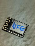
This evening after a session of DarkMatter great progress was made on the SonoffMQTT project. This project aims to replace the firmware on a Sonoff with custom firmware so that it is accessible via MQTT instead of the supplied eWeLink. Having it available on MQTT means it will plug directly into Home Assistant and will be cointrollable from there. After soldering some headers into the board, I was able to power it externally (not mains) and flash it using Arduino IDE.
Sunday, 27th May 2018 - 23:43:48
Written by on May 27, 2018 .
Sunday, 27th May 2018 - 16:33:36
Written by on May 27, 2018 .
Sunday, 27th May 2018 - 13:41:23
Written by on May 27, 2018 .
Tuesday, 22nd May 2018 - 15:19:57
Written by on May 22, 2018 .
Thursday, 3rd May 2018 - 23:08:55
Written by on May 3, 2018 .
Thursday, 12th April 2018 - 20:45:36
Written by on April 12, 2018 .
Saturday, 10th February 2018 - 10:21:46
Written by on Feb. 10, 2018 .
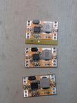
I received a dodgy batch of DC-DC converters. These are pretty common 12-19V in and 3.3V out. The top one is a dodgy one from the supplier. The bottom one is working unit from another supplier. You can see that the resistor and capacitor (between inductor and chip and between chip and bottom left solder pad) are transposed. They probably just loaded the wrong reels. I can fix these but it's a pain in the butt. The seller ended up giving me a partial refund. The middle is where I've desoldered the R and C and swapped them to their correct positions. The issue, however, is that the R is incorrect also resulting in 3.6V... I'll need to buy some parts and fix them.


