


During the weekend I upgraded Fedora on my laptop from Fedora 13 to Fedora 15 using the preupgrade utility. This initially took a lot of messing around. The main problem of capacity in the /boot partition was self-inflicted. When I created the partition layout for the system, I only allowed 100MB. This meant that there wasn't enough room to install the upgrade installer boot files to that partition.
Resizing the /boot partition, which was ext3, took a number of steps.
First, it was necessary to convert to ext2. All the utilities required can be found on Hiren's Boot CD by booting into small linux, knoppix would also be a good choice. First, tune2fs is used to convert from ext3 to ext2 by removing the jounal (-O ^has_journal). Once that is done, some space must be made to expand the boot partition. In my layout I removed the swap partition which is directly after to /boot. The friendliest way to do non-straight forward manipulation (i.e. resizing) of the partition table is with gparted. Start gparted and delete the swap partition, then resize the /boot partition to 250 meg. The next thing to do is resize the actual file system to occupy all of the partition. resize2fs is used to expand and shrink ext2 filesystems.
The other important thing I should mention: remove all your custom repos where possible i.e. Adobe et al. Otherwise preupgrade will go hunting for preupgrade packages at those repos (and fail).
Once all that was sorted, preupgrade was left to run overnight downloading about 2.6 gig of rpms.
In the morning I was presented with a reboot button. Once rebooted, the real work starts. Updating 2000 odd packages. This ran for most of the morning but once complete, it worked well with no major problems yet.
Author archives: timd
Monday, 7th November 2011 - 08:49:43
Written by on Nov. 8, 2011 .

Saturday 29th October 2011 - 23:48:13
Written by on Oct. 30, 2011 .
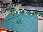
I managed to make it out to the lab for a bit today.
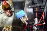
I added a relay to the kids electric ride on Jeep replacing on/off with forward/reverse. They never turn the damn thing off anyway! I bypassed the on/off switch and cabled it separately. Originally the on/off and "go" buttons were in series. The on/off now energizes a relay for reverse, when unpowered the NC position on the relay is forward. I used a simple DPST reverser configuration where the power enters the NC terminals then crosses over to the NO terminals creating a polarity switch. The motor is fed from the centre common terminals.
Also on the list - a white noise generator. After messing around a few nights ago and not getting anywhere, I tried another circuit. This time using BC548s and a 12V supply. One BC548 is reverse biased and the E-B junctions zener effect is used as a noise source. The base of the reverse biased BC548 is then fed into the base of another BC548 to be amplified and then coupled with a 10uF cap to another BC548 for further amplification. At one point while I was messing around it was receiving radio - probably from the audio amp section. The whole thing is on a bread board, so its not that protected from interferance.
Monday 17th October 2011 - 07:38:30
Written by on Oct. 17, 2011 .
Owner finally decided to fix the sewer properly after 3 months. Yaaay
Saturday 15/10/2011
Written by on Oct. 15, 2011 .
Unproductive Saturday. Watched the plumber try to jet blast the sewer most of the day as well as trying to help him with some bugs in his jetblast system. He just replaced the water tank in his truck and hadn't drilled a breather yet. The high pressure pump tried to turn the plastic drum inside out - and nearly did... We had to reprime the pump too because it was full of air.
Spent the rest of the day on the veranda with a beer watching the kids play (and giving hugs to stem crying / breaking up their fights =P )
Monday 3rd October 2011 - 18:45:31
Written by on Oct. 4, 2011 .
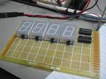
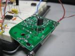
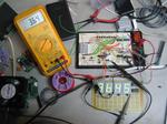
Today I messed around with the "f88 and got the code working to push updates to the three multiplexed displays in parallel. The controller, once completed, will be fitted to my dummy load. One A2D will read the voltage on the 1R shunt giving me current, the other will measure the input voltage. During the update process, the pic multiplies these two and gives a third readout in watts. These three figures are then pushed out to three shift registered with linked clocks and latches. Three four digit displays with just 5 IO.
Saturday 1st October 2011 - 18:51:01
Written by on Oct. 1, 2011 .
Today I worked on the door counter project. I was inspired by Dave Jones' EEVBlog #204 and decided to do some of the math (which I'm really not great at and should practice!) instead of just throwing a pot in and then measuring it after.
Because of the overhead in the encoder/decoder arrangement and wireless, a pulse of at least 250ms is required before the other end reacts. This took some messing around with the scope and poking with a bit of wire to work out. When the relay on the door laser clicks, the pulse is very short, maybe 20-30ms.
To stretch out the pulse I used the 555 timer in monostable mode. Pin 2 of the 555 is pulled high by a 10k resistor. The output (pin 3 of the 555) is tied via a resistor to the base of a transistor. The transistor, an NPN BC548, is sitting across the pushbutton on the transmitter with its collector on the +5v side. When a falling edge (high to low transition) is detected on pin 2 of the 555, pin3 goes high for a fixed length pulse (unless pin 2 is maintained low for longer than the pulse time). The pulse length can be calculated using t (time) = 1.1RC.
With a desired pulse time of 250ms we can work out the resistor and capacitor required. I chose 10uF to start with and worked out R from there.
Here is a scope grab. It worked out pretty close.

Saturday 1st October 2011 - 09:14:38
Written by on Oct. 1, 2011 .
Grass! It's like the day of the Triffids here. I couldn't mow last weekend because it rained. I've been thinking more and more about a project to use servos. I think a small lawnmower engine PID with throttle on a servo would be cool which regulated the revs. Later, a full RC mower.
I've got to finish off the door counter (which I mentioned as finished in an earlier blog). The counter hardware it's self is finished, but I need to write software for the linux box and I also need to make TX/RX arrangement to send the door clicks to the counter. The original plan was to have the whole unit next to the door and run a long serial cable. I've sinced decided that we're going to use some 315MHz TX and RX modules from work which means I need to make an monostable oscillator to extend the pulses long enough to make it through the RX and TX modules - if they are too short, they don't register at all. I am thinking at least 100ms.
Sunday 11th September 2011 - 23:26:32
Written by on Sept. 12, 2011 .
I have finished off the door counter for work. We will see how helpful it is. I might put in the serial link today so that I can link it into the server.
Now to write a python daemon to monitor the clicks on the serial port!
Friday 26th August 2011 - 08:51:39
Written by on Aug. 26, 2011 .
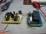
I am currently working on a door counter. I have based it on the 16f84A (I bought a tube of them years ago before I worked out they weren't really that great). In keeping with the ancient PIC, I found ancient schmitt trigger to debounce. The TP4304. Its stamped '78. I scored a bunch of old CMOS from a closing electronics store.
http://www.datasheetarchive.com/dl/Datasheets-112/DSAP0044783.pdf
Sunday 21st August 2011 - 18:22:09
Written by on Aug. 21, 2011 .
Got lots of work done on my 4 digit multiplexed display. The prototype is up and running with an ADC demo on the pic. It's running 100hz refresh rate with 5hz data refresh rate.
Tuesday 9th August 2011 - 18:02:42
Written by on Aug. 9, 2011 .
I have had a request to prepare a TG watchdog for installation inside a PC. To do this I am using the router to supply it power (as normal) and I have prepared a ribbon cable to go straight into the mainboards COM IDC header - rather than piggybacking ouside to a D9 socket and back in.
I also had the idea to use the TG watchdog as a means of powering down the box it lives in. Because it is powered externally to the server it lives it, it could reset or power down the system. I have some stuff I bought from mouser - 2 way inline SIL sockets and plugs. I'll have to post photos and part numbers. You could make a wedge cable to short the power or reset pins on the mainboard while leaving the button function intact.
Wednesday 27th July 2011 - 07:52:47
Written by on July 27, 2011 .
I now have Hi-Tech C running under piklab. I'm glad that I tried it now.
After messing around for an evening or two with a stupid problem where bitwise OR assignments "|=" on PORTA and reading the value on PORTA fails, I decided that maybe SDCC was bugged. The OR would appear to work, but on closer inspection they actally zeroed the byte I was working on and only set the single bit that I was specifying. I installed MPLAB 8.73 with the Hi-Tech C compiler for 10/12/14/16 MCUs. There was trouble initially with wine as the picc.exe executable lived under "Program Files", So I moved the folder down to the home directory. This brought me a step closer as piklab verified the files exist - when it came to compile time piklab still tried to execute the linux executable rather than the .exe. I symlinked sdcc.exe to sdcc and libr.exe to libr and it now works fine.
Straight away I tried a compile (which failed) and then started the port from sdcc to picc. Once I had finished, the project built ok and I burned the hex to the pic (an 'f88). Lo and behold the same error occurred!
The code I used was originally an experiment with the adc which I wrote previously to try out SDCC. After combing the net I found a FAQ on the Hi-Tech website which described exactly my fault! I had a read of the FAQ and then checked out my code. Doh! I had remmed out the ANSEL declaration rather than implicitly setting it to 0. Facepalm.
Saturday 23rd July 2011 - 20:15:43
Written by on July 23, 2011 .
Last night I decided to try SDCC again. It works much nicer than the last time I tried it. It also managed to make it work correctly with Piklab.
I have the USART and basic stuff running on a breadboarded TG watchdog.
Thursday 7th July 2011 - 20:38:20
Written by on July 7, 2011 .
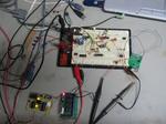
I am learning LTSpice and have finally worked out how to sweep a resistor value over time in an LTSpice simulation. I tried all sorts of stuff to make it work, but didn't think of this novel way of doing it. Drive the resistance by multiplying the total resistance by a 0-1v sweep (and add say 0.001 so LTSpice doesn't cry). Unfortunately I can't take credit for this idea myself - it came after lots of googling and forum trolling. I've incorporated this sweep into my new constant current load simulation. This sweep starts after a delay of 2s.
The first part of the simulation (first 2s) concentrates on the low battery indicator. The vbattery voltage sweeps from 12v up to 24v over 2s so that we can see the battery voltage cross the low battery set threshold and the vlowled indicator fall.

In the top plot area you can see the traces for the battery after the resistor divider (vlowsens), the low battery threshold voltage set with a zener diode (vlowset), the output from the opamp to drive the low battery LED (vlowled) and the +15v output from the LT1121.
In the middle plot we can see the amount of current being sourced and by multiplying the voltage on the high side of R1 by the current on R1, we can see the power in watts.
The bottom plot area shows the linear response of the pot simulating the rotation of the dial for its full range over 10 seconds. It crosses over in the middle where the wiper is at exactly 50%.
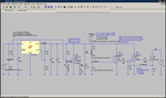
There are also a few more notes and photos in the gallery.
Friday 17th June 2011 - 13:08:01
Written by on July 2, 2011 .
Off sick today.
Watching some Red Dwarf on DVD. Best quote ever:
http://www.youtube.com/watch?v=GgAJDIbMK9M at 7:25
KRYTEN: Computing time to impact... calculations coming through - here they come.
LISTER: How long have we got?
KRYTEN: About the time it takes to read a stop sign, sir.
Sunday 19th June 2011 - 14:36:23
Written by on June 19, 2011 .
I have just finished removing the old clothes line which the tree loppers destroyed. Unfortunately it was an original hills hoist. The centre aluminium casting is smashed. The clothes line is incredibly over-engineered. 50mm main tube, 5mm wall thickness! The stringers that hold the arms up are 1/4" solid steel bar. The concrete block the base is set in presented a big problem. The slab is approx 400mm wide and 500mm deep. I actually bent the box trolley transporting the thing.
To get the slab out I had to use a combination of leverage (framing pine - I bent a star picket using that), back-filling and a really big hammer.
First I dug around the edges about 200mm (one shovel width) on two sides after realising how huge the slab was. I dug under one corner and then sheared the corner off with a few solid hits of the hammer. The slab was unaffected by the hammer when it was encased in earth. Next I had to tip the slab over into the hole because there was no hope of moving it until I got rid of the "suction" effect the wet ground had on the slab. To raise it out of the ground I used leverage and back-filling. Once near ground level I was able to push it up and over the edge using two pieces of framing pine as levers.
Suprisingly the new clothes line only has a plastic insert to set into the slab. The insert is just 340mm deep!
Sunday 12th June 2011 - 21:07:51
Written by on June 12, 2011 .
I have successfully revived the new laptop. Unfortunately, the spare lid and panel I received (for a different model) has a different mounting system, a straight panel/inverter swap was out of the question. Where the original panel is more inset to the lid with the mounting tabs on the glass side with standoffs extending from the back of the lid, the the new panel is flat on the rear of the lid with mounting tabs on the backlight side.
After assessment and a bit of testing I decided to fit the whole spare back lid to the laptop. Some modification was required. I had to modify the hinge mounting plates to fit the hole arrangement in the laptop and remove some of the plastic molding in places.
The machine was left running with a small stick of RAM running memtest with the screen on. Later in the day I returned and found it had passed successfully several times. I then removed the harddrive and RAM from my old laptop and fitted it to the new laptop.
If I had been running Windows on the original laptop, this probably would have posed a problem, thankfully I have Fedora 13 on it. The old laptop is intel based, the new AMD based. All that was required initially was to switch xorg over to the VESA driver temporarily until the machine came up on the new laptop and had the propriety ATI binary drivers installed. It "just works". Nice.
Sunday 12th June 2011 - 08:29:10
Written by on June 12, 2011 .
I scored a laptop with a dead screen just in time for my laptop to fail. Although my laptop didn't fail entirely - just the backlight. I took it apart last night and repaired the backlight. The bundle of tiny tiny tiny wires which traverses the hinge to drive the screen had one broken wire. It took a lot of peeling to get to the wires. The bundle is wrapped in a metallic/cloth weave with glue backing on one side. Once open I was able to solder the wire. I used a piece of silicone wire sheath from a halogen down light (since it needs to be really flexible) rather than heat shrink to protect the joint.
The laptop I scored appeared to have a dead screen. It was given to me with a spare screen. After about 40 screws I separated the top and bottom plastic molded section from the cast aluminium inner frame and gave everything a clean and a bit of an eyeball. I then ran the system up to see what was going on. The screen was entirely dead. I left the screen in place and plugged in the spare screen. It fired up nicely but the plug didn't quite seat correctly. There were bent pins in the socket. Out with the maggie lamp and the pointy tweezers! I straightened the pins and plugged in the original screen. Voila! The screen fired up, but it looked like it was toast anyway. There was a red band across the bottom. I don't know how the replacement screen fired up without those pins - but the original does not... Perhaps the plug, cabling or controller is damaged as well.
Today I will be swapping out the original LCD panel and hopefully, although the plugs are the same, hopefully the mounting system is the same. If it is - I've got a working laptop.
Wednesday 1st June 2011 - 19:40:53
Written by on June 1, 2011 .
I've just watched the Beowulf trailer after looking at some random videos in YouTube. Near the middle of the trailer they play "In the House - In a Heartbeat" which is the theme for 28 Days / 28 Weeks Later. Makes me want to break out Left for Dead II and fwap some zombies! I haven't played that in aaages.
Wednesday 1st June 2011 - 12:02:53
Written by on June 1, 2011 .
Got a few bits on clearance from Rockby. Large 7 segment LED modules and some SMD 5V relays. Cool.